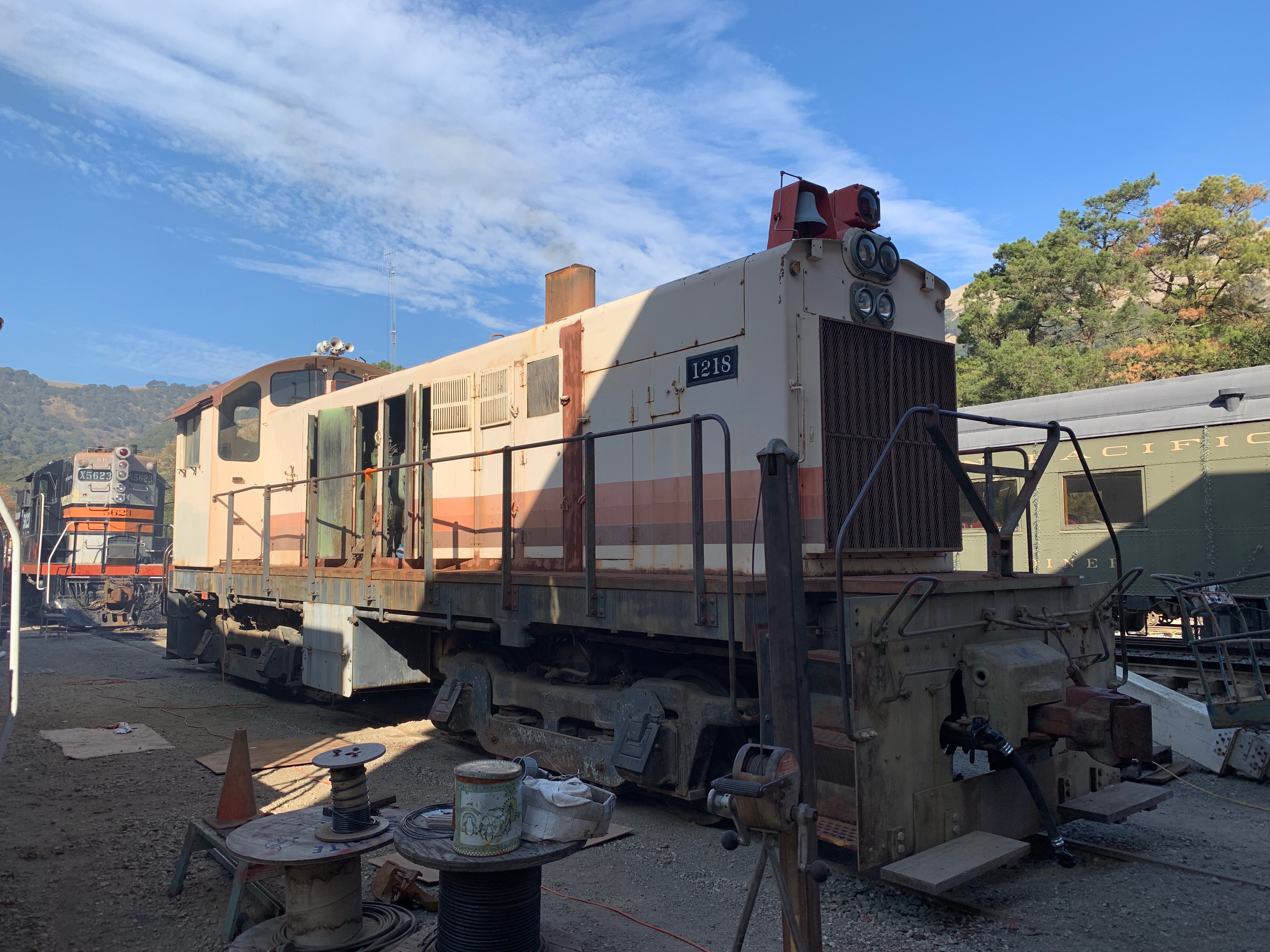
SP 1218 is an Alco S-6, shipped in late
June 1955 as
SP 1051, the last of 19 in SP's first order
for the S-6 which was assigned class DS-9.
She was renumbered in the 1965 system-wide renumbering and became part of
class AS409-1. Bloody Nose paint seems to have occurred close to the time
of the renumbering; so far no photographic evidence has appeared to confirm
which came first.
Standard electrical equipment was a GE GT-533 main generator and GE 731
traction motors but SP ordered the larger GE GT-584 main generator, and
probably GE 752 traction motors.
After retirement from the Southern Pacific, SP 1218
went to work for Foster Farms Chickens. The current livery is a remnant of
working for "the chicken people" though the plan is to return her to her final
SP livery (Bloody Nose).
The first problem I helped with involved an electrical fault. Howard Wise
and I have since spent a lot of time with the
electrical diagram for WM 151 and 152.
Western Maryland's S-6s have some minor differences but are close enough
for what we need and we don't have an SP diagram.
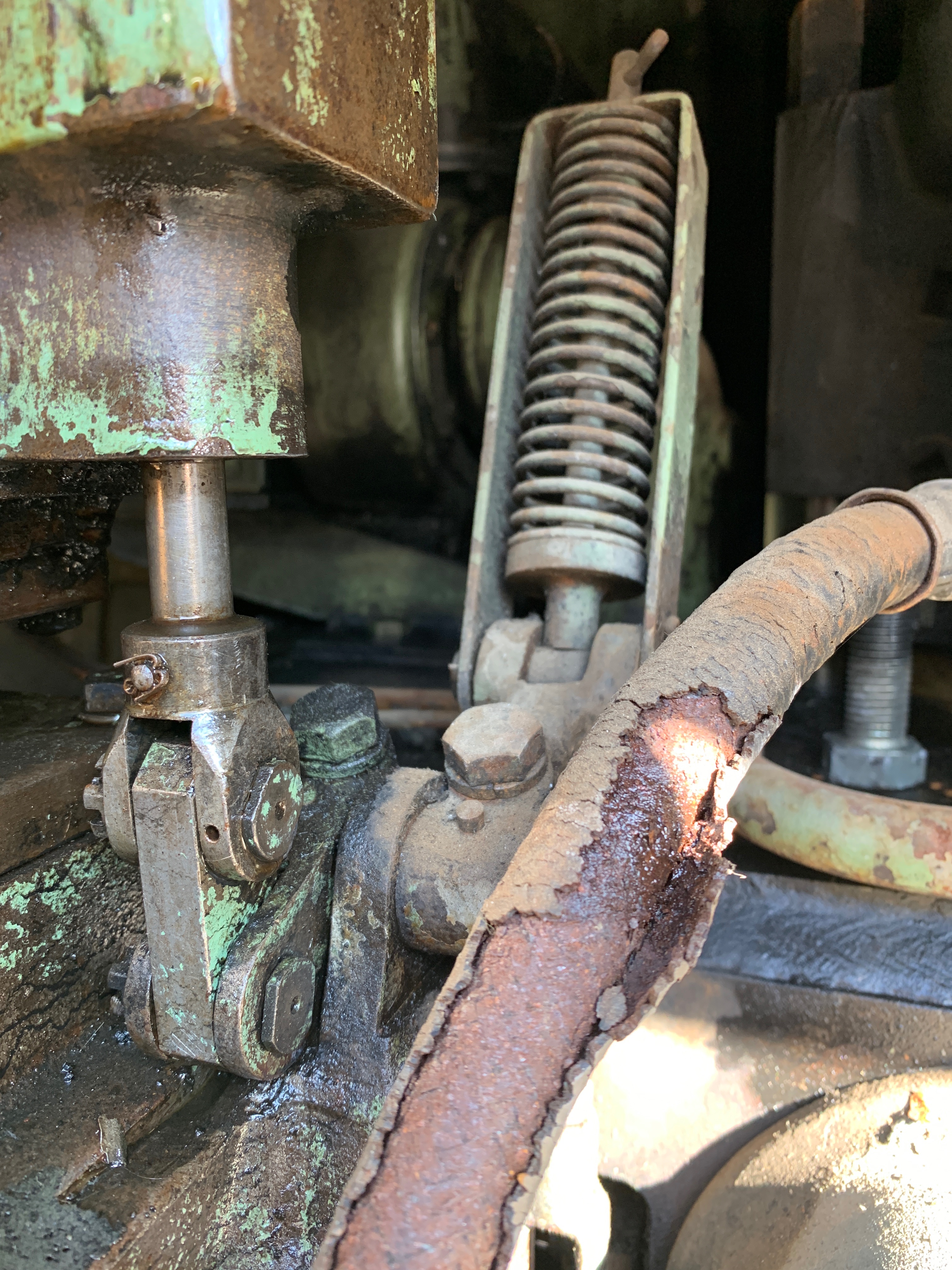
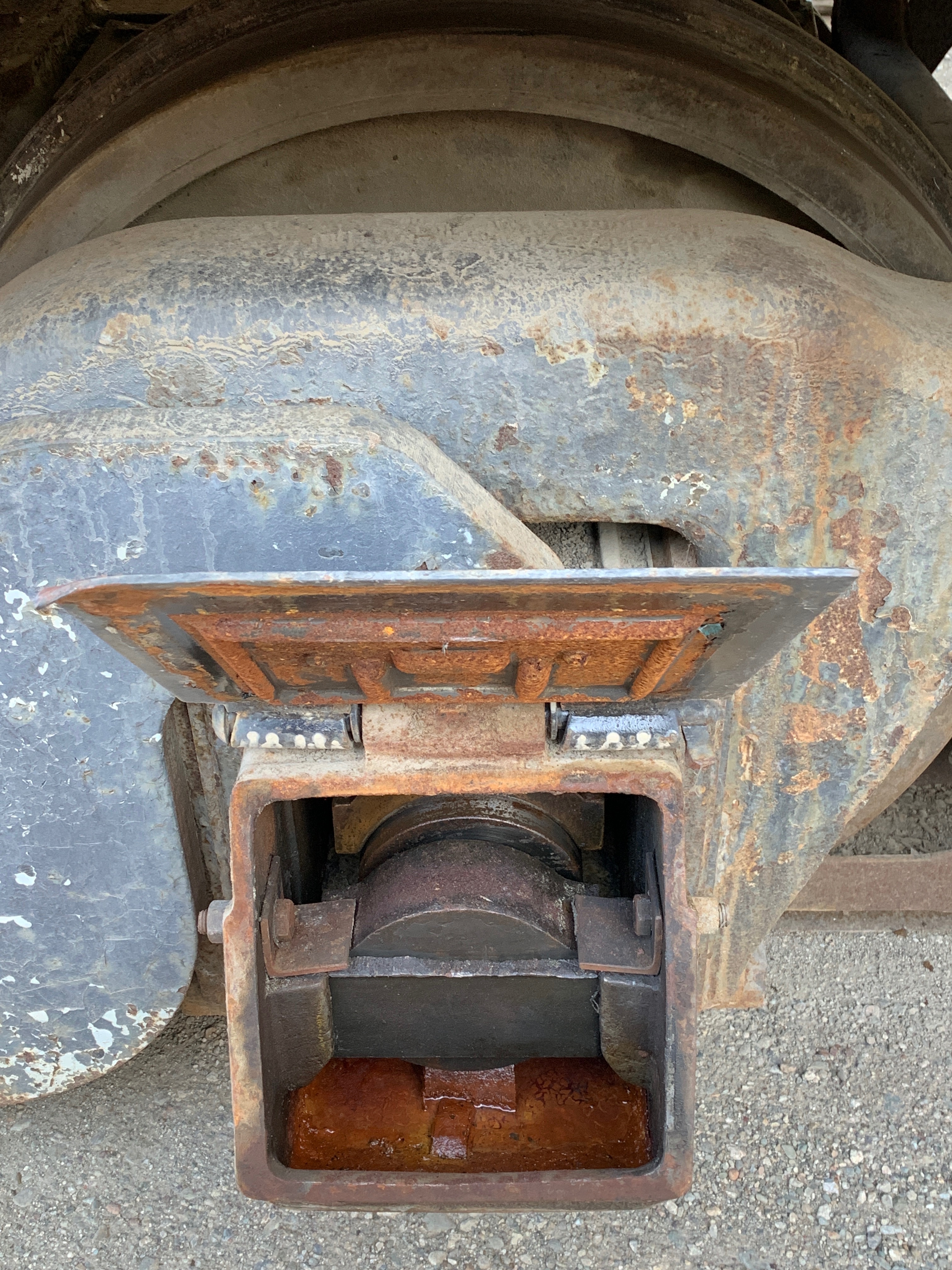
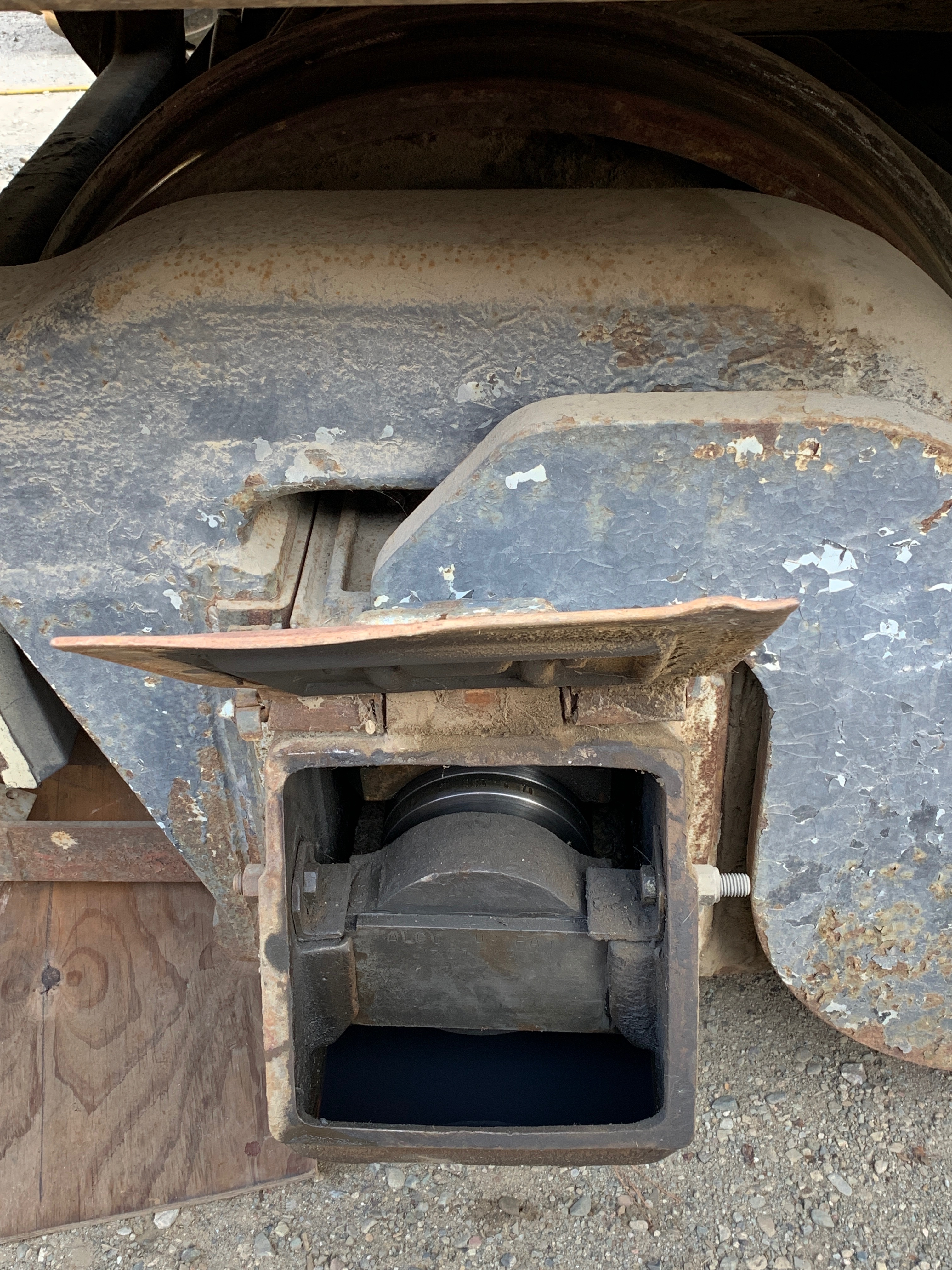
Water got into the journal-bearing box for the #1 axle on the right side
of the locomotive. The #2 axle shows how it ought to look.
Introduction
Electrical Diagram
Squawks
Work Session on 9 December 2020
 |
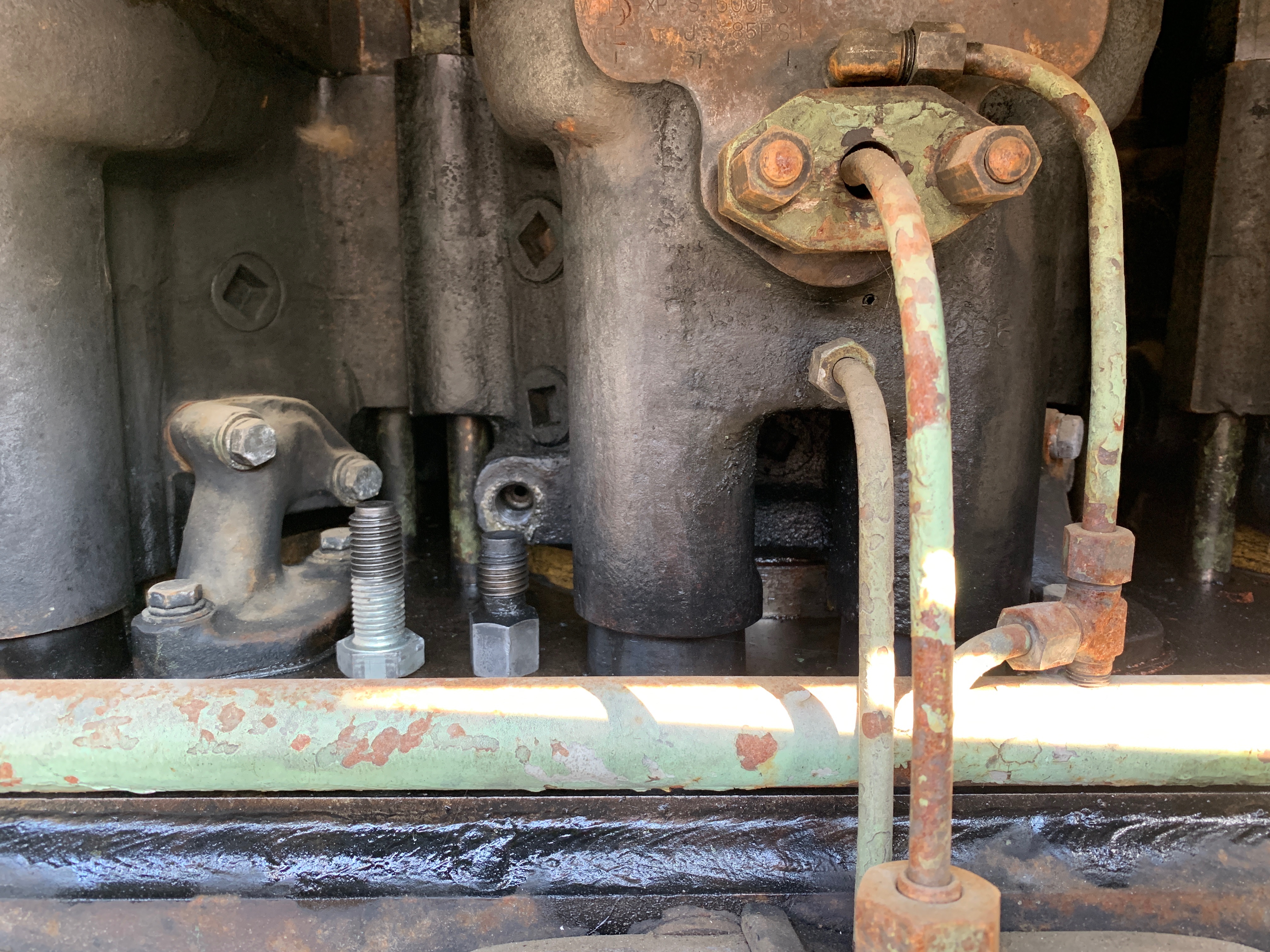 |
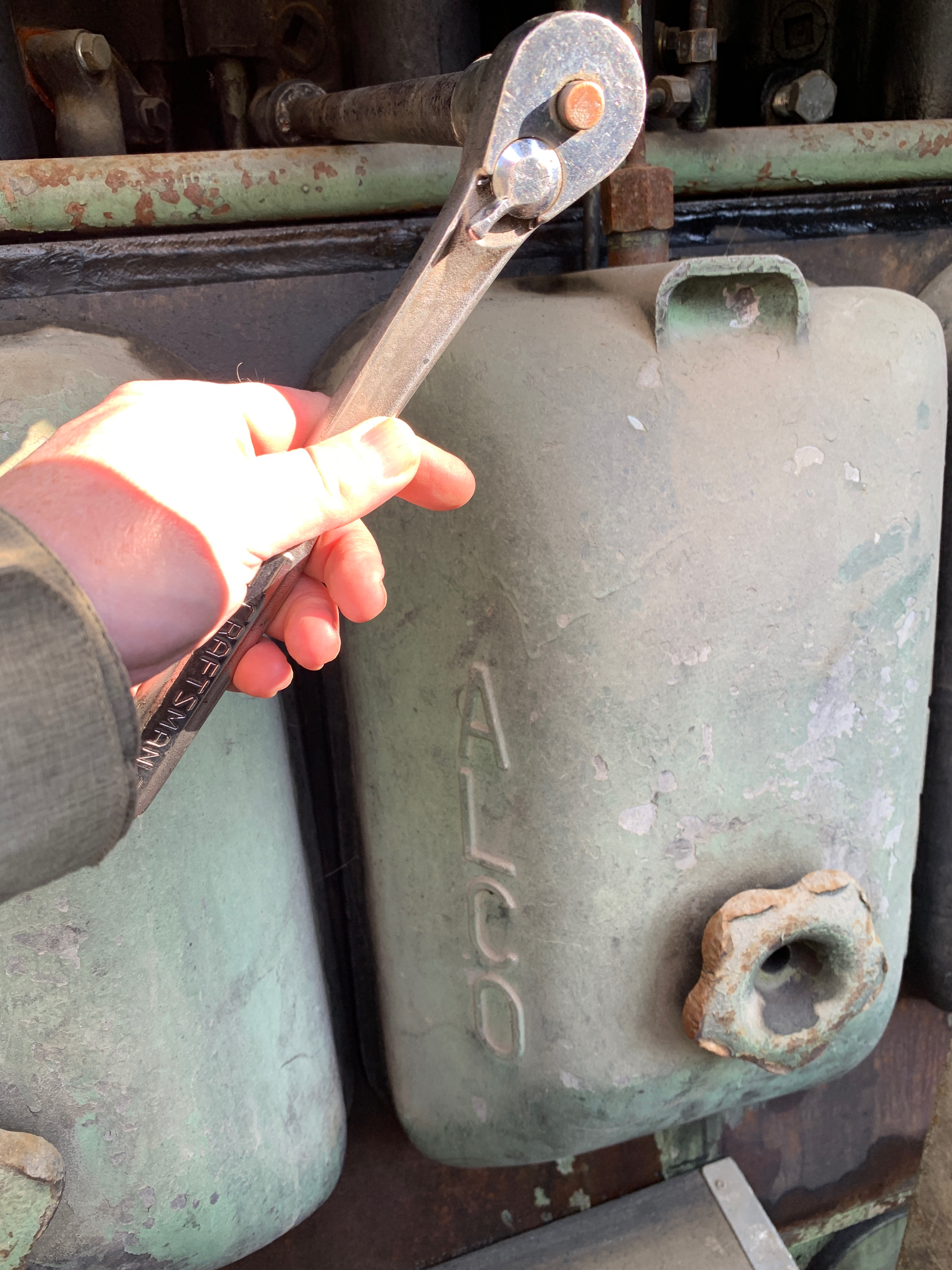
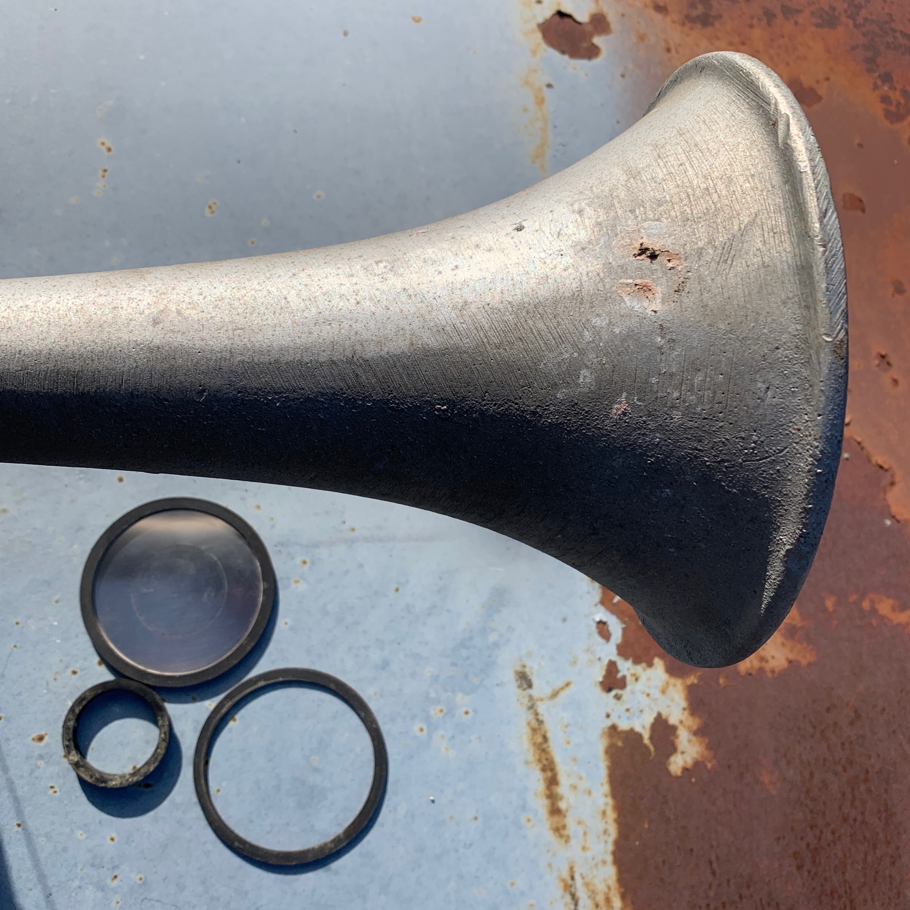
Removing the cylinder drain plugs. In the second photograph, the short plug on the right (underneath where it is normally installed) is an original Alco plug. The longer one to its left is one improvised by Howard Wise at the Niles Canyon Railway.
The fuel line's outer layer was flaking off and, under pressure, seeped a little but not enough to be a concern for a brief test run. (Howard subsequently replaced it with a new one.)
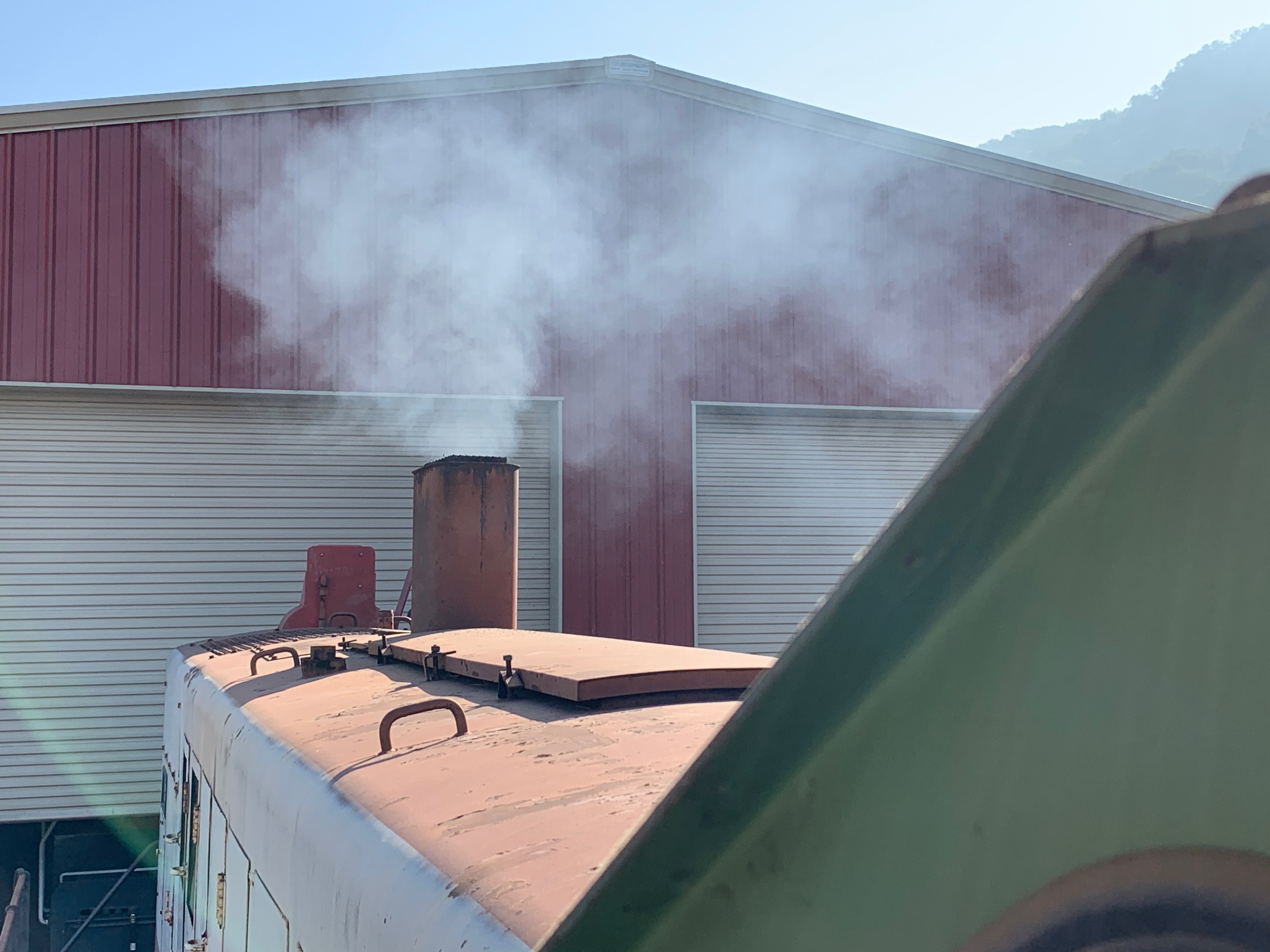
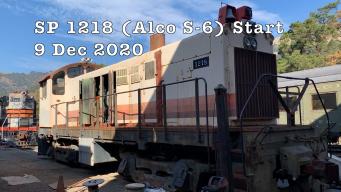
The 6-cylinder inline 251 engine fired up with surprising ease, emitting the smoke which earned Alco Diesels the nickname "honorory steam locomotives."
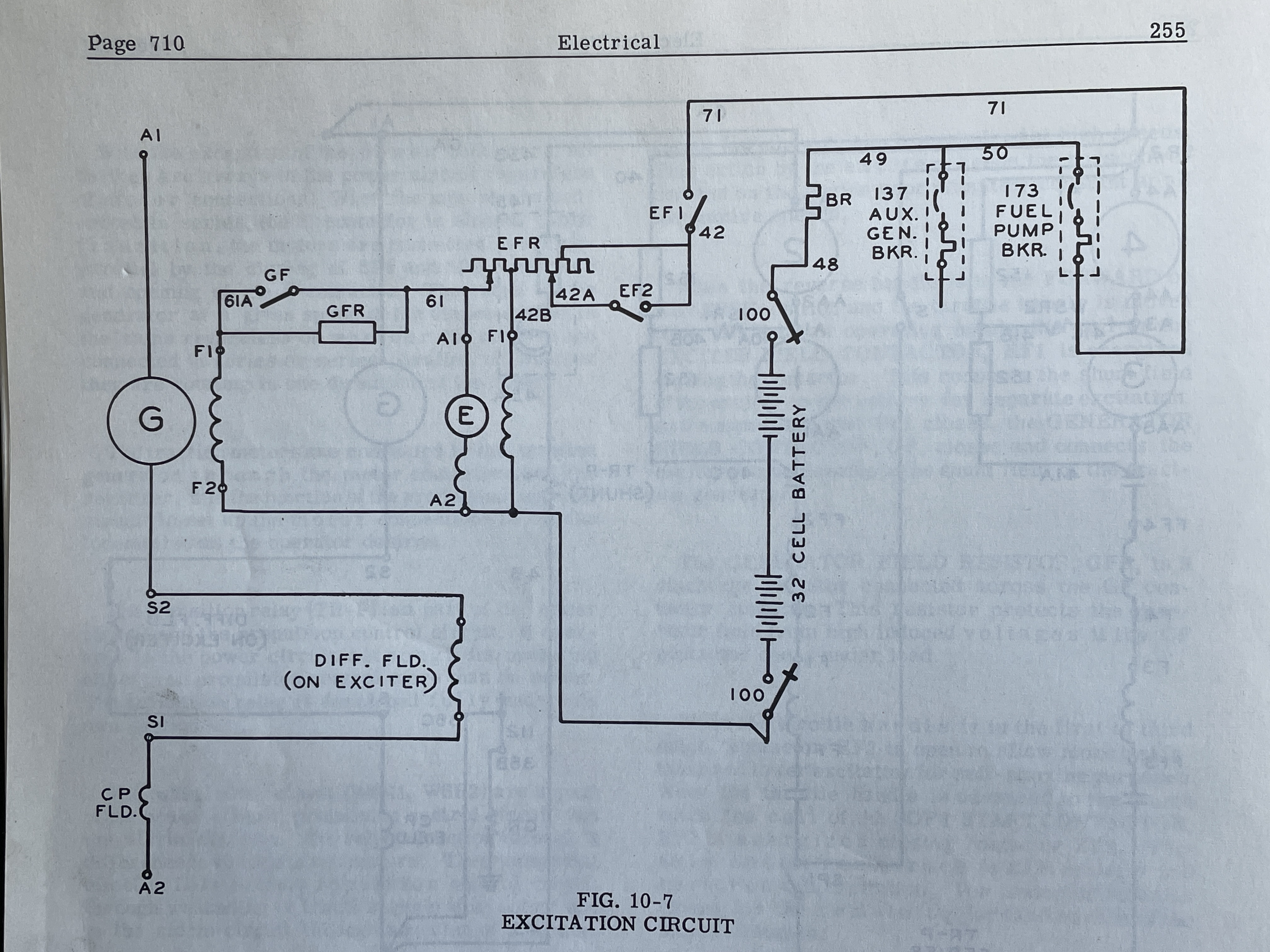
Considerable work in March 2024 was devoted to trying to understand why the
main generator was not generating power, whcih seemed to be due to the
generator field not being excited. This investigation focused on
Section C of the
electrical diagram:
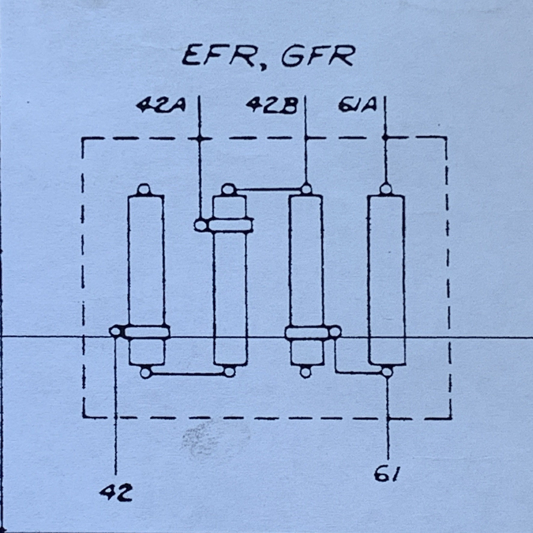
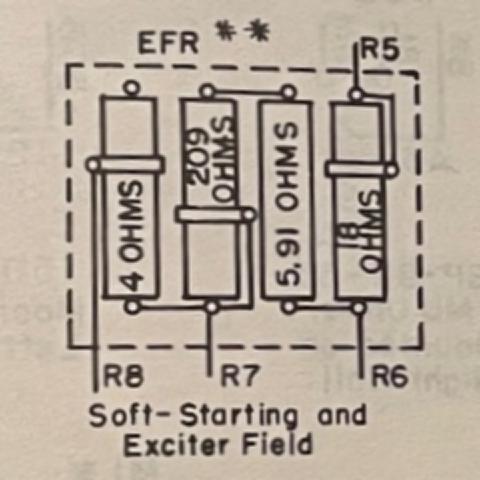
This diagram shows EFR (Exciter Field Resistor) as one resistor and
GFR (Generator Field Resistor) as a separate resistor. These devices
are actually composed of four large reisistors grouped together, with
adjustable sliders connecting to them. The three resistors on the left
of the group comprise EFR with the rightmost resistor being GFR. The
connectors and resistances are as follows:
Work Sessions during March 2024
![]()
 Copyright © 2020-2021,2023-2024, Karl L. Swartz. All rights reserved.
All trademarks mentioned herein belong to their respective owners.